By Tom Curatolo, Principal Applications Engineer
As motherboard loads and load power began to increase and density became even more challenging, power systems architecture evolved from a distributed DC-DC converter (or Brick) to IBA (Intermediate Bus Architecture). With IBA, a converter steps the 48V input down to 12V and multiple niPOLs (non-isolated point-of-load regulators) buck the 12V down to specific load voltage requirements. Power system architectures adapted to solve the new challenges of a changing communications, computing and industrial world, driven by ever-increasing performance demands.
Today’s power requirements and lower (<<1V) PoL operating voltages, are placing new demands on IBA that now affect system performance. The increase in power and dynamic-load requirements of many of today’s loads (CPUs, GPUs, AI processors) demand that their voltage regulators (VRs) be located as close as possible to the load input power pins. This significantly reduces power losses through printed circuit board or substrate copper power planes referred to as the Power Delivery Network, or PDN.
Additionally, many loads require extremely high-current transient response (di/dt), which motherboard impedance can impact.
However, placing high-current voltage regulators close to high-power loads does have drawbacks for IBA due to the large number of VRs (niPOLs) required to support the high power. This in turn requires more space, leading to increased distance (impedance) from the load and lower overall efficiencies due to increased losses and subsequent lower dynamic performance. The conversion ratio of 12 to <<1V is also a serious obstacle for the multiphase buck niPOL array due to duty cycle limitations.
Factorized Power: The solution to today’s new power challenges
Summarizing the trending challenges for power system design:
- A very high current delivery capacity, from 500 to 2000A
- Loads requiring high dynamic performance
- Large PDN losses and impedances
- Expanding use of the 48V bus infrastructure, requiring a 48V to sub-1V capability
Solving this high-current and high-density point-of-load (PoL) problem requires a different approach. Factorized Power Architecture™ (FPA™) is the solution.
Distributed power architecture and IBA both consist of conversion and regulation stages to get down to the point-of-load voltages. In the case of IBA, the regulation and conversion stage (Buck Regulators, niPOLs) follows the conversion stage IBC (Intermediate Bus Converter). Factorizing these architectures delivers:
- Voltage transformation (converting a voltage from one level to another)
- Voltage regulation (controlling the converter output voltage to a target value even when the input voltage varies)
A regulator has optimum efficiency when VIN = VOUT and loses efficiency as the regulator's input-to-output ratio increases. With a typical input voltage varying between 36 and 60V, the optimum output bus voltage would be 48V instead of the legacy 12V bus that is typical of IBA. A 48V output bus requires four times lower current than the 12V bus (P = V•I) and PDN losses are the square of the current (P = I2R), which reduces losses by 16 times. So placing the regulator first and regulating to a 48V output will achieve the highest efficiency. As can be seen in this example, this regulator must accept an input that can sometimes swing lower than 48V, necessitating a buck-boost regulating stage to satisfy this aspect of the design. Once the input voltage is regulated, the next step is to convert the 48 to 1V.
In the case of a 1V load requirement, the best transformation ratio would be 48:1. In that case, the regulator bucks or boosts the input to a 48V output and the transformer steps down the voltage from 48 to 1V. Given that a step-down voltage transformer increases current by the same ratio, an equivalent name for the transformer component is a Current Multiplier. In this case a 1A input current would be multiplied to 48A out. To minimize PDN losses of the high-current output, the current multiplier needs to be small so it can be positioned as close to the load as possible.
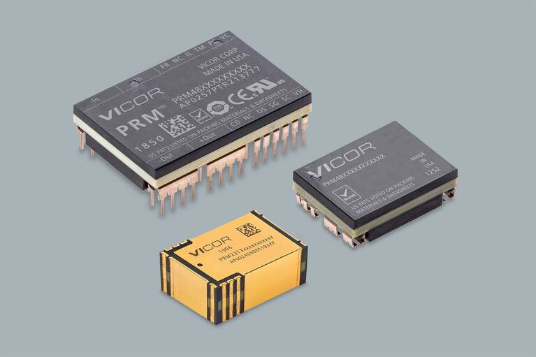
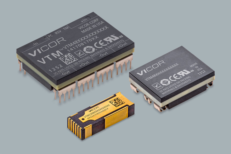
PRM™ Regulators and VTM™ Current Multipliers combine to form the Vicor Factorized Power Architecture. These two devices work in partnership with one another, each fulfilling its specialized role efficiently to enable the complete DC-DC conversion function.
The PRM supplies a regulated output voltage, or ‘factorized bus’ from an unregulated input source. This bus feeds a VTM which transforms the factorized bus voltage to the level needed by the load.
Unlike IBA, FPA does not step down from an intermediate bus voltage to the PoL through series inductors. Instead of averaging down the intermediate bus voltage, FPA uses high-voltage regulation and “current multiplier” modules (VTM) with a current gain of 1:48 or higher to provide higher efficiency, smaller size, faster response and scalability to 1000A and beyond.
The components behind factorized power
The PRM and VTM are the components that make FPA possible. The PRM uses a patented Zero‑VoltageSwitching (ZVS) buck-boost regulator control architecture to give high-efficiency step-up and step-down voltage regulation and soft start; maximum efficiency is achieved when VIN = VOUT, with 99.3% peak being achieved with the latest PRMs.
The VTM current multiplier is a high-efficiency voltage transformation module using a proprietary Zero‑Current Switching / Zero-Voltage Switching (ZCS / ZVS) Sine Amplitude Converter (SAC™). It operates on a pure sinusoidal waveform with high spectral purity and common-mode symmetry. These characteristics mean that it does not generate the harmonic content that the typical PWM type conversion has and generates virtually minimal noise. The control architecture locks the operating frequency to the powertrain resonant frequency, allowing up to 97% efficiency and minimizing output impedance by effectively canceling reactive components. This very low, non-inductive output impedance allows it to respond almost instantaneously to step changes in the load current.
The VTM responds to load changes regardless of magnitude in less than one microsecond with an effective switching frequency of 3.5MHz. The VTM's high bandwidth obsoletes the need for large point-of-load capacitance. Even without any external output capacitors, the output of a VTM exhibits a limited voltage perturbation in response to a sudden power surge. A minimal amount of external bypass capacitance (in the form of low ESR/ESL ceramic capacitors) is sufficient to eliminate any transient voltage overshoot.
Energy storage and dynamic response the FPA™ way
For faster load transient response that is often required in demanding applications such as radar and ATE test heads, the SAC™ topology by virtue of employing a fixed-ratio converter has the advantage of not imposing the bandwidth limitations of an internal control loop struggling to maintain regulation. Thus, the VTM™ powertrain offers a unique capacitance-multiplication feature.
Figure 1
For example, the effective output capacitance is 2300 times the input capacitance when a VTM with a K of 1/48 is used. This means significantly less capacitance would need to be added downstream of the VTM.
Energy (E) stored in a capacitor is:

Therefore, a small amount of capacitance at the 48V input to the VTM has the same effect as the bulky capacitance typically added to the 1V output of the multi-phase buck converters that are typically the niPOLs used in IBA.
Figure 2: FPA reduces capacitance and saves board space
The benefits of FPA™
Factorized Power Architecture™ enables power system density and high-current demands to keep pace with rapidly advancing CPU, GPU and ASIC technologies. Some key advantages when designing a systemwith these power components include:
- Reduced real estate consumption near the CPU/GPU by 50% or more
- Reduction by an order of magnitude in PDN and associated board losses
- Unfettered performance by placing the PRM & Digital Controller in non-critical board edge areas
- Simplified CPU I/O routing
- Mitigated risk of placement near the processor's SerDes because of lower noise performance of the VTM
- Ability to meet higher power needs because VTMs can be easily paralleled
Overall efficiency for a power system – including the combination of a PRM and a VTM – operating from an unregulated DC source and supplying a low-voltage DC output typically ranges from 90 to 95%. With higher efficiency comes lower total heat dissipation, another important consideration in power
systems design.
FPA: a scalable solution that can meet future demands of board-mounted power
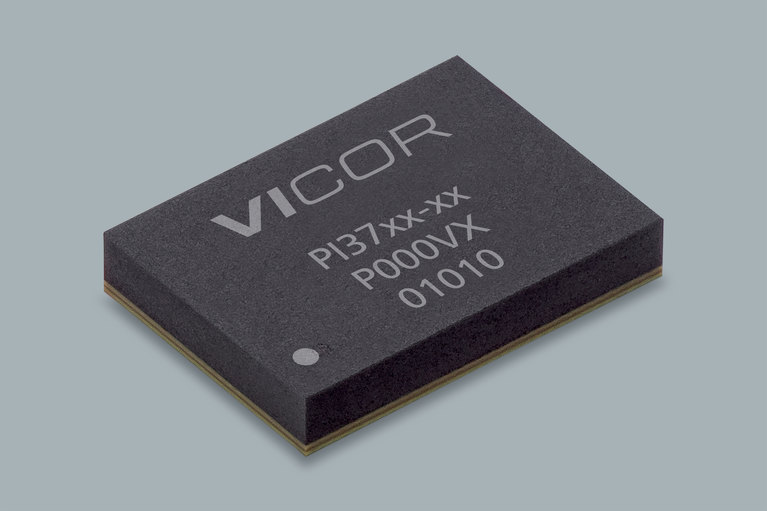
As load currents continue to increase, Vicor has continued to enhance FPA to maximize current delivery and to further reduce density and the PDN to the point-of-load. Today Vicor offers a factorized Power‑on‑Package solution, consisting of MCDs (Modular Current Drivers) and MCMs (Modular Current Multipliers), where only the secondary side of the former VTM’s transformation stage is located at the point-of-load. The regulation stage and the primary side of the VTM are now co-packaged into the
MCD. The MCM can be mounted on the same package/substrate as the high-current processor. The MCD, as is the case with a PRM, can be mounted far away from the current-multiplier stage, using board real estate that is not as critical for density.
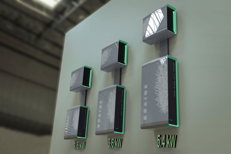
Increasing numbers of applications are leveraging Factorized Power Architecture by providing 48V direct to PoL power conversion for CPU, GPU, ASIC and memory loads. This enhanced performance has been a boon for Artificial Intelligence (AI) computing, Radar and Automotive ADAS (Autonomous Driving and Safety) applications, where the demands for high density, high efficiency and low noise, outpace the conventional methods of power conversion.