2026 年汽車創新日
Vicor 展示了使用緊湊、高功率密度的 DC-DC 轉換的創新優勢
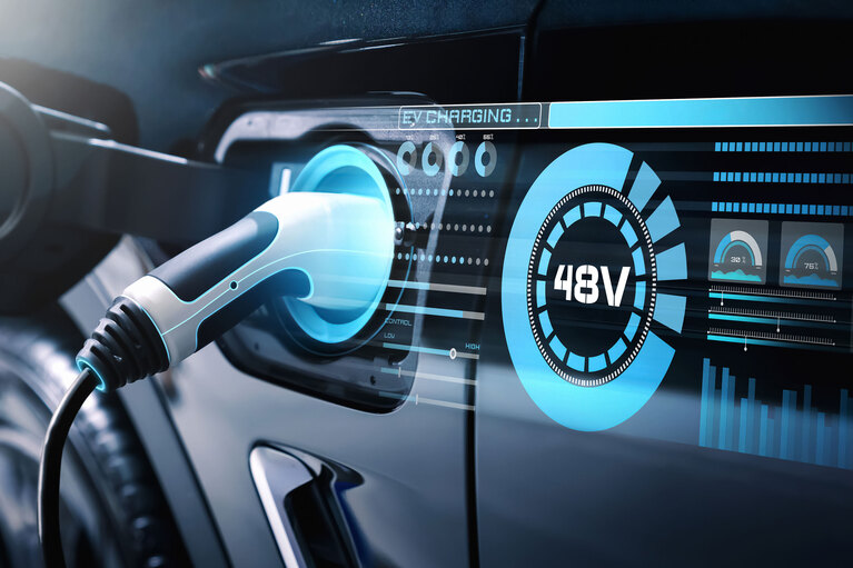
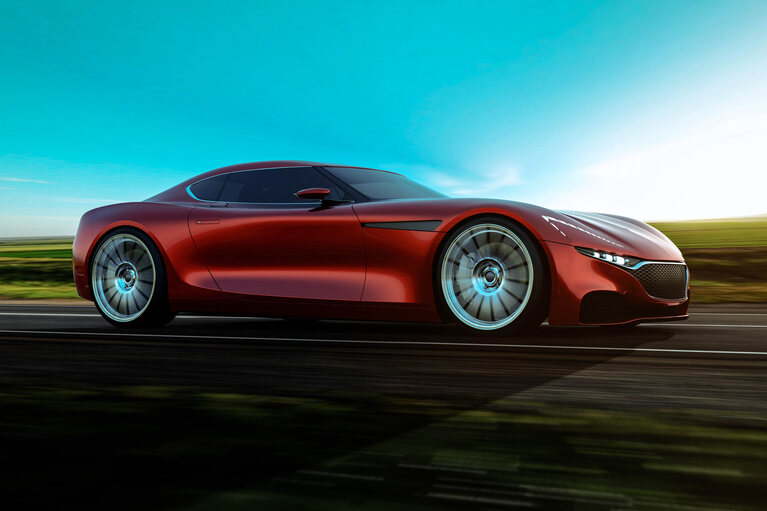
採用 Vicor 的 NBM 模組,原始設備製造商(OEM)無需改造整個動力系統即可使用 800V 電池,從而節省時間和精力。
與高級戰略應用/系統工程師 Nicola Rosano 的問答
問:在著手應對電磁干擾(EMI)挑戰之前,需要掌握哪些關鍵知識?
答:有效排查 EMI 故障需要扎實的實踐經驗。電磁相容(EMC)領域並非所謂的“玄學領域”。有些問題可以借助相關書籍解决,而有些問題則需要對實際物理系統進行精細調試。掌握以下四個方面的背景知識,能最大限度地减少測試中的失誤,為用戶節省大量時間。這些知識包括:
每個電源設計師遲早都會發現,在設計的最後階段,最可能導致返工的三大難題往往是:熱管理問題、安全相關問題或頑固的電磁干擾(EMI)問題。其中,EMI問題最難預測,因為它像一個名副其實的“氣球”。如果我們試圖“壓制”一個頻段的發射頻譜,它就會在另一個頻段“鼓出”。因此,常常發生這樣的情况,當傳導發射達標時,輻射發射可能又超出限值,反之亦然。電源系統中的EMI整改極具挑戰性,部分原因在於大量雜散的寄生參數會發揮作用,它們相互影響、競相作用。因此,難以完全避免實驗室調試。電磁領域的規則就是:所有電氣設備需彼此友好共存,成為“好鄰居”——既不會對其他設備造成過多干擾,也不會對其他設備的干擾過於敏感。
問:傳導發射和輻射發射過高的主要危害是什麼?
答:電磁相容(EMC)可分為四個領域:傳導發射、輻射發射、傳導抗擾度和輻射抗擾度。
開關電源(SMPS)最容易出問題的就是前兩個領域:傳導發射和輻射發射。在這種情況下,EMI 過高的主要危害可概括如下:電磁干擾(EMI)、元器件應力、合規性問題、射頻干擾(RFI)、訊號失真和效率降低。 控制傳導和輻射 EMI 的主要目的是防止一個電力系統的發射干擾第二個或第三個系統。對此,消費者最直觀的感受就是EMI干擾車載娛樂系統的無線電訊號,導致音質變差或訊號遺失。從操作方面看,過量的 EMI 可能降低車內所用數據訊號的質量,甚至導致車輛無法讀取所有必要的數據,從而無法滿足排放和安全合規要求。
問:解决 EMI 問題的傳統方法及其各自的權衡取捨有哪些?
答:解决 EMI 問題的主要傳統方法及其各自的權衡取捨包括:輸入輸出濾波器、遮罩、接地技術、緩衝電路、擴頻技術開關。在這些方法中,確保良好的接地路徑以及功率級拓撲的選擇和控制至關重要。 如果功率級採用硬開關,產生的高水准 EMI 和開關損耗會使得實現 MHz 級的高切換頻率變得極其困難,甚至幾乎不可能。 此外,如果接地處理不當,設計人員在測試中僅靠濾波器無法有效解決 EMI 問題。因此,良好的佈局設計往往比濾波器設計更為關鍵。這也解釋了為何部門間的緊密合作對整個開關電源(SMPS)的開發和量產至關重要。
問:在 EMI 深度檢測中,哪個元器件被視為被測設備(DUT)?
答:要準確理解這一點,首先要瞭解一下被測設備(DUT)。NBM9280 是一款可貼片安裝、非穩壓、非隔離、雙向、高效 DC-DC 轉換器,之所以選擇它,是因為其具有超高切換頻率及車規級認證。它的峰值效率達 99%,主要用於汽車行業中的 800V/400V DC-DC 轉換。它尺寸緊湊,僅為 92 × 80mm,卻能處理 30kW 的功率流。NBM 通常充當 DC-DC 快速充電樁(額定電壓為 400V,放置在汽車外部)和高壓電池(額定電壓為 800V,放置在汽車內部)之間的介面。 除電流共享功能外,NBM 的主要優勢之一是它允許任何 OEM 在不改造整個動力系統的情况下使用 800V 電池,從而顯著减少工作量和時間。
問:共模(CM)譟音如何影響被測設備(DUT)?
答:若以接地(GND)為參考量測 NBM 金屬外殼上的雜訊,會觀測到其方波形雜訊類似於 NBM 內部高壓快速開關節點的雜訊。這種雜訊相對固定,基本不受負載變化影響,也就是說,即使負載發生變化,諧波含量也基本保持不變。如果 NBM 金屬外殼與外部阻抗網路(LISN)直接相連,可使用接地探頭檢測金屬外殼相對於接地面的諧波含量。 如果將金屬外殼與接地路徑隔離,就可以有效抑制共模雜訊分量,從而减少傳導發射測試中的整體雜訊。
問:解决被測設備(DUT)共模(CM)雜訊的主要技巧是什麼?
答:使用分佈式旁路電容器有助於通過降低雜訊改善共模效能。實驗證明,在同樣的背景下,在高 dv/dt 區域附近分佈式放置電容器能顯著降低共模雜訊。另一種方法(與前述方法相輔相成)是通過在電源線周圍使用鐵氧體磁環,使電線中的電流相互抵消,從而降低交流雜訊分量。這一方法可有效降低紋波,大幅削弱 EMI 頻譜强度。外部鐵氧體還有助於减少任何不平衡電流分佈。
問:符合 CISPR 32 標準的濾波器拓撲有哪些?
答:主流濾波器拓撲有三種:L 型、π 型和 T 型。只要設計得當,任何一種拓撲均可將總體雜訊降低到限值以內。 在我提到的案例中,我採用了 L 型拓撲,因為其在測試過程中實現起來更簡便且成本更低。
問:使用高工作頻率的優缺點是什麼?
答:在功率相同的情况下,高頻率是小元器件的代名詞。因此,重量輕和體積小無疑是一個優勢。但另一方面,開關損耗往往會隨著頻率的新增而新增。良好的設計策略是選擇高頻率並採用諧振拓撲。諧振拓撲是先進的開關電源(SMPS)設計,可在任何頻率下消除開關損耗,實現超高的效率。
問:本次研究的主要經驗教訓是什麼?
答:就本次案例研究而言,主要經驗教訓如下:
Nicola Rosano 於 2022 年加入 Vicor,擔任歐洲、中東和非洲地區(EMEA)高級戰略應用與系統工程師,提供汽車電源系統相關的技術支援和諮詢。在加入 Vicor 之前,他曾在 Thales Alenia Space 和 Airbus Defense and Space 的軍事、國防和太空部門工作,還曾在 BorgWarner 和 Stellantis 的汽車業務部門擔任過高級硬體電源系統工程師。 他擁有多項專利,並正籌備在 YouTube 上開通一個類比/電力電子學教育頻道。他目前的研究重點包括電力電子學、電路和系統、電子儀器以及工程教育。Rosano 於 2010 年獲得電氣工程學士學位,並於 2013 年以優异的成績獲得了碩士學位。
作者:Nicola Rosano,高級戰略應用與系統工程師