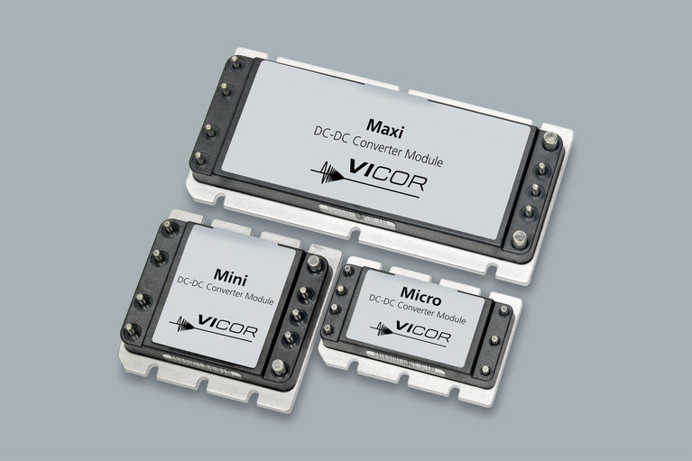

VIPAC Array™ family
VIPACアレイは、柔軟性に優れたDC入力の電源システムで、薄型ののコールドプレートシャーシに最大4つのユーザーが任意に設定可能な出力を構成できます。VicorのPowerBenchコンフィギュレーションツールを使用して、電源設計者は24,28,48,72,110,150,300または375 VDCの入力で最大出力が600 W、2〜54VDCから出力電圧を選択するVIPACアレイを構成することができます。
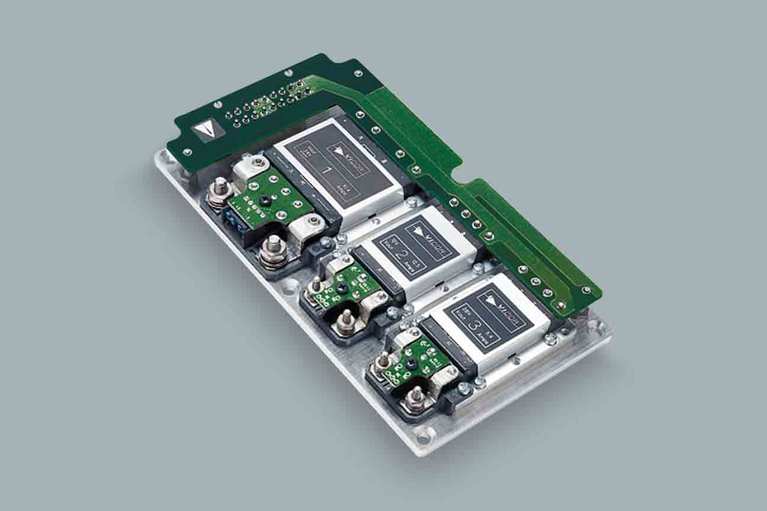
VIPACアレイは、高電力密度で信頼性の高い分散型およびモジュール式の電源システムとして使用できます。
現在、出力電流シェアリングオプションは単一出力モデルで利用可能であり、大電力/冗長性を必要とするアプリケーションで使用できるようになります。入力コネクタおよび出力端子を使用することによりシステムの組み立てが簡単になり、汎用性の高い放熱板により放熱設計が容易になります。
Single, dual, triple & quad outputs
Fully connectorized
input & output for simplified hook up
Rugged, low-profile, coldplate chassis
High-temperature capability
VIPAC Array™ family
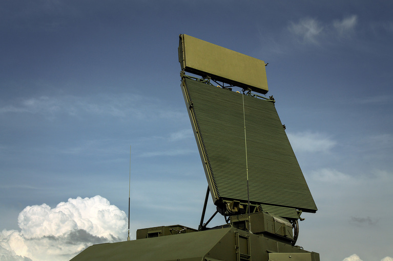
The future of standardized defense platforms using MOSA, SOSA and VPX open architectures
The future of standardized defense platforms using MOSA, SOSA and VPX open architectures
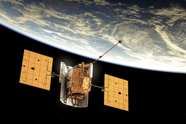
Delivering higher power density and low noise for New Space applications
Patented power design techniques and architectures needed to deliver optimal power and low noise for space communications applications
Optimizing DC-DC converter stability: AC and transient analysis in simulations of source impedance effects
Learn how to optimize DC-DC converter stability through AC analysis in the frequency-domain and transient analysis in the time-domain