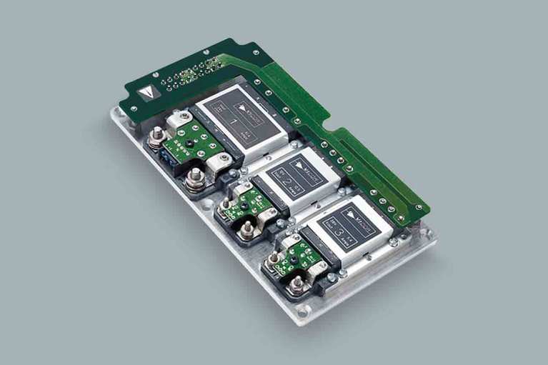
VIPAC Array™ family
VIPAC Array™ DC Configurable Power Supply
The VIPAC Array is a highly flexible system of DC input, power building blocks that can be configured with as many as four user-definable outputs on a low-profile, coldplate chassis. Using the Vicor PowerBench™ configuration tool, designers are able to specify VIPAC Arrays with inputs of 24, 28, 48, 72, 110, 150, 300 or 375VDC and outputs from 2 to 54VDC at power levels up to 600W per output. VIPAC Arrays are ideal for use in distributed and modular power systems where power density and reliable operation are critical.
A current-share option is available on single-output models enabling them to be used in applications requiring high power/redundancy. Fully connectorized input and output terminations speed system installation and a versatile coldplate chassis simplifies thermal management.

Power System Designer
Features and Benefits
Features and benefits
Single, dual, triple & quad outputs
Fully connectorized
input & output for simplified hook up
Rugged, low-profile, coldplate chassis
High-temperature capability
Resources
Resources for the design engineer

Active suspension systems in electric vehicles
48V power systems reduce losses and downsize power designs. Vicor is making the transition from 12V to 48V easier, delivering a competitive advantage

DC-DC power modules help to bridge the 48V/12V transition
EVs and data centers have transitioned to a 48V architecture to enhance power performance. The new Vicor family of DC-DC converters are aiding that move

Unlocking the secrets of the universe with precision adaptive optics
Adaptive optics using Vicor’s power dense modules, help Microgate mechanically deform telescope mirrors to better resolve deep space images
- cURus – UL 60950-1, CSA 60950-1
- cTÜVus – EN 60950-1, UL 60950-1, CSA 60950-1
- CE Mark – Low Voltage Directive (2014/35/EU)
- CE Mark – Low Voltage Directive (2014/35/EU) and RoHS Recast Directive (2011/65/EU)
- CB Certificate – IEC 60950-1
- Outline drawing for VIPAC Array Configuration "A"
DXF PDF - Outline drawing for VIPAC Array Configuration "B"
DXF PDF - Outline drawing for VIPAC Array Configuration "C"
DXF PDF - Outline drawing for VIPAC Array Configuration "D"
DXF PDF - Outline drawing for VIPAC Array Configuration "E"
DXF PDF - Outline drawing for VIPAC Array Configuration "F"
DXF PDF - Outline drawing for VIPAC Array Configuration "G"
DXF PDF - Outline drawing for VIPAC Array Configuration "H"
DXF PDF
- Using LugMate, 1 Output
STEP 3D PDF - Using LugMate, 2 Outputs
STEP 3D PDF - Using PlugMate, 1 Output
STEP 3D PDF - Using PlugMate, 2 Outputs
STEP 3D PDF - Using LugMate, 2 Outputs
STEP 3D PDF - Using LugMate, 3 Outputs
STEP 3D PDF - Using PlugMate, 2 Outputs
STEP 3D PDF - Using PlugMate, 3 Outputs
STEP 3D PDF - Using LugMate, 2 Outputs
STEP 3D PDF - Using LugMate, 3 Outputs
STEP 3D PDF - Using PlugMate, 2 Outputs
STEP 3D PDF - Using PlugMate, 3 Outputs
STEP 3D PDF - Using LugMate, 1 Output
STEP 3D PDF - Using PlugMate, 1 Output
STEP 3D PDF - Using LugMate, 2 Outputs
STEP 3D PDF - Using LugMate, 3 Outputs
STEP 3D PDF - Using PlugMate, 2 Outputs
STEP 3D PDF - Using PlugMate, 3 Outputs
STEP 3D PDF - Using LugMate, 2 Outputs
STEP 3D PDF - Using LugMate, 3 Outputs
STEP 3D PDF - Using LugMate, 4 Outputs
STEP 3D PDF - Using PlugMate, 2 Outputs
STEP 3D PDF - Using PlugMate, 3 Outputs
STEP 3D PDF - Using PlugMate, 4 Outputs
STEP 3D PDF - Using LugMate, 1 Output
STEP 3D PDF - Using PlugMate, 1 Output
STEP 3D PDF - Using LugMate, 1 Output
STEP 3D PDF - Using LugMate, 2 Outputs
STEP 3D PDF - Using PlugMate, 1 Output
STEP 3D PDF - Using PlugMate, 2 Outputs
STEP 3D PDF
Promo Component
Related Products
Related Products

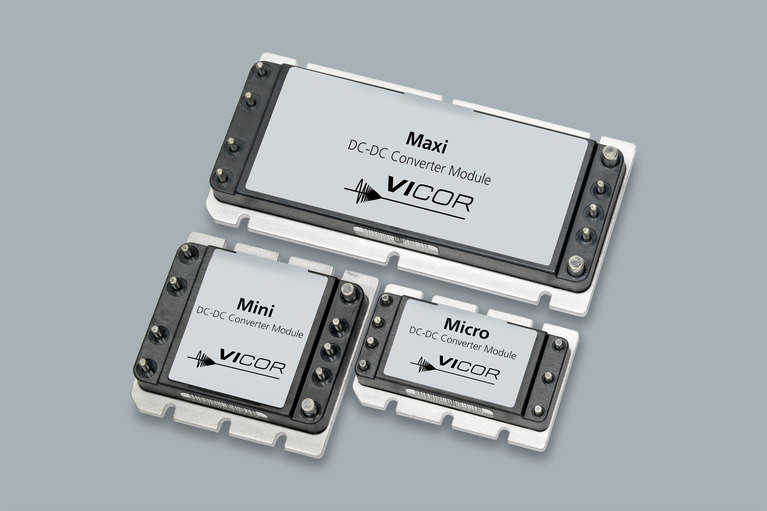
The DC-DC converter that established the “brick” standard