


Optimizing DC-DC converter stability: AC and transient analysis in simulations of source impedance effects
Learn how to optimize DC-DC converter stability through AC analysis in the frequency-domain and transient analysis in the time-domain
Tutorial by Jonathan Siegers, Principal Applications Engineer and Vamshi Domudala, Application Engineer
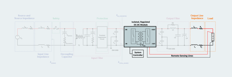
The previous tutorials in this series addressed the appropriate filtering, stability, and protection concerns for power modules when used as elements of a complete DC-DC power system. This tutorial is focused on the load-specific aspects of a system designed with power modules.
It was once possible to conceptualize the load supplied by a DC-DC module as merely having voltage and current requirements, effectively reducing it to a simple black box. But loads have grown in complexity over the years, and today they have many characteristics relevant to the power delivery network (PDN). Therefore, power system designers must understand the behavior of the load in considerable detail to determine whether it can impact the performance of the DC-DC module. For example, the load might affect the module’s control-loop response and, therefore, its ability to regulate and perform in a stable manner. The load’s behavior might also adversely affect the module’s transient response capabilities.
Every system involves some design considerations that are particular to the load (orange elements of system diagram).
Every system involves some design considerations that are particular to the load (orange elements of system diagram).
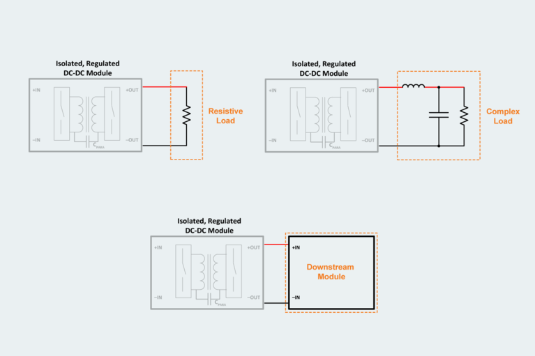
There are three main load types: resistive, complex, and downstream converters. Resistive loads are the simplest, having no impact on the DC-DC module’s control-loop or transient response at all. A more complex load comprised of resistive, inductive, and capacitive characteristics will certainly impact the module’s control-loop stability and transient response. But the situation becomes less obvious when a DC-DC module is the input to an additional converter module. In this case, the upstream module’s control-loop stability and transient response depend on the control-loop characteristics of the downstream module. In addition to these main load types, some special cases require more careful analysis.
Three basic load types—resistive, complex, downstream power module.
Three basic load types—resistive, complex, downstream power module.
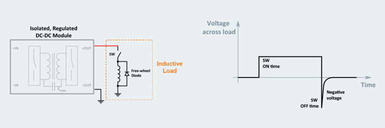
Inductive loads present particular challenges for DC-DC power modules at the instance of turn-off. In the following figure, the characteristics of an inductive load are shown for a simple inductor and series switch. Opening the switch breaks the current path from the module to the inductor very quickly, producing a large negative voltage spike as the inductor impedes the change in current passing through it. This action results in a high-frequency noise pulse and, potentially, arcing across the open switch contacts. The voltage spike applied to the DC-DC module’s output (and anything else connected to the bus) can affect the module’s behavior, and the noise pulse will impact the module’s EMI and overall performance. The solution is to add a freewheeling diode connected across the inductive load to provide the required discharge path for the inductor’s stored energy.
Inductive loads have unique features affecting power system design, notably large negative voltage spikes in the instance of switch-off.
Inductive loads have unique features affecting power system design, notably large negative voltage spikes in the instance of switch-off.
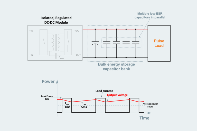
Pulse loads, characterized by brief but very high peak load currents, present a different kind of DC-DC system design challenge. The simplest way to design a system for this kind of load is to choose power modules that support the full load current at the peak of the pulse. While this works, it has significant negative trade offs in terms of weight and cost of both the power modules and the associated filtering and thermal management components they require.
It is possible to design a more compact and less costly system using the power-averaging technique. Average power is a function of the peak load requirement and the ratio of on-time to off-time. A power-averaging system design utilizes a smaller DC-DC module and appropriate PDN components for bulk energy storage to keep the voltage drop within the load’s specified tolerance during the off-time of the duty cycle. This optimizes the power system for actual power needs, rather than overdesigning the system for the worst-case condition.
The power averaging technique allows designers to optimize DC-DC systems for loads that require high-current power in short-duration pulses.
The power averaging technique allows designers to optimize DC-DC systems for loads that require high-current power in short-duration pulses.
There are several factors affecting the selection of an appropriate power module for power averaging. First, the module must operate with a current and power limit to ensure that the load’s peak pulse will draw power from the bulk energy storage capacitor bank placed at the output of the power module. Second, the DC-DC module must support start-up and operation with large output capacitance, as significant energy storage may be needed depending on the pulsed load characteristics. Large output capacitance can also impact the module’s stability and must be accounted for in the system design.
Three main considerations influence the selection of appropriate capacitors for the bulk storage designed into the PDN. First, the voltage rating should be about 140% (or more) of the system’s operating voltage. Second, select capacitors with appropriate temperature profiles so that environmental conditions involving a significant amount of heat will not adversely affect system reliability. Lastly, weigh these performance factors against the physical volume of the capacitance acceptable in the application.
One of the major advantages of the modular approach to DC-DC system design is scalability: power modules enable current sharing and offer fault-tolerance when used in parallel, which offers the benefit of increased reliability while providing a considerable amount of power without having to qualify a new discrete design. It is sometimes possible to connect power modules in parallel without much concern about adverse interactions with their respective control systems, but designers should be aware of two main areas of interest.
First, it is important to be aware of any applicable power de-rating that might alter the standalone module’s capabilities when used in an array. For instance, modules in an array might not start up into the same full-load capacitance as a standalone module. Second, additional external control circuitry may be required to ensure that the shut-down and restart behaviors of modules that encounter faults do not disrupt the entire system.
To make full use of the capabilities offered by modules connected in parallel, the system design should ensure that the array evenly shares the load current. This will maximize the overall reliability of the array by reducing the thermal stress on each module. The simplest approach is to adopt a droop-sharing mechanism so that as the load draws more current, the output voltage sags slightly and enforces current sharing among the modules. A more complicated method is to add an active current-sharing controller that monitors each module’s individual output current.
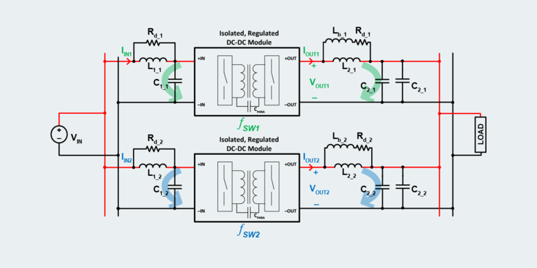
Parallel arrays of modules also need a filter design for the input and output to ensure that the noise currents generated by a module circulate locally and do not create interference with adjacent modules. If allowed to circulate freely in the array, the noise currents can produce serious stability problems and adversely affect overall system operation.
Filtering on each module’s input and output in a parallel array prevents beat frequencies (represented as green and blue arrows) from circulating throughout the array and causing system instability.
Filtering on each module’s input and output in a parallel array prevents beat frequencies (represented as green and blue arrows) from circulating throughout the array and causing system instability.
One of the ways switching noise can affect system stability is the addition of a low-frequency noise component to the system’s overall switching frequency noise profile. A beat frequency like this is caused by the inherent variability that exists even among modules of the same type and model number, complicating in the real world what would ideally be a single higher-amplitude ripple made by summing the switching noise of all the modules in the array.
Another reason to design and include input and output filtering for each individual module is that the normal noise created by one module can be perceived by another module in the array as a perturbation and therefore cause a drastic change in that module’s behavior, even though the load’s behavior remained constant. Return to the second tutorial in this series for more on output filter design (Part 2).
Parallel arrays of modules also make fault-tolerance possible by means of redundancy, significantly improving the reliability and stability of a DC-DC power system with only a modest increase in cost. A system load might have power requirements that a single module could supply, but by adding another module in parallel, the system achieves N+1 redundancy. Multiple modules in parallel achieves N+M redundancy.
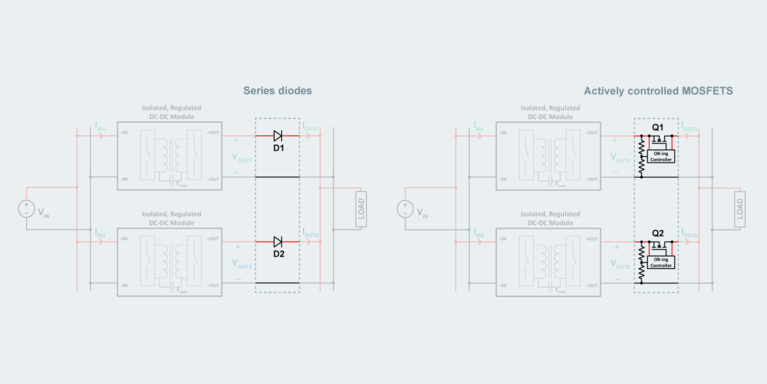
Specific implementation will vary by application, but the fundamentals are essentially the same: OR the outputs of the modules together to prevent a fault or short circuit from shutting down the entire array. There are two ways to accomplish this: a series diode or actively-controlled MOSFET placed at each module’s output. A series diode will block a short circuit condition at the output of one module from affecting the rest of the array. Still, it will incur some power losses due to the forward voltage drop when conducting current during normal operation. To mitigate the losses, take advantage of the diodes’ negative temperature coefficient by running them hot. To further reduce losses, substitute an actively-controlled MOSFET for the diode: it will perform the same function as the diode but with a lower efficiency penalty.
There are two options for OR-ing a redundant array of modules to ensure a fault in one module does not bring down the whole system: series diodes and actively controlled MOSFETS.
There are two options for OR-ing a redundant array of modules to ensure a fault in one module does not bring down the whole system: series diodes and actively controlled MOSFETS.
Loads consistently demand more from power supplies, making discrete solutions more cumbersome to design with each passing year. Pressures include more power, better quality power, higher efficiency, scalability, tight design schedules, and a host of other challenges. The modular approach to power design offers clear advantages that allow power designers to keep pace, but designing with power modules means thinking differently and employing some new tools and techniques. Taking the time to understand the modular approach is clearly worthwhile because power modules are steadily getting smaller, more efficient, and more capable.
This tutorial series provides a beginning-to-end overview of the process for designing DC-DC power systems with modules: from basic power system architecture (Part 1) to noise filtering and stability considerations (Part 2), (Part 3), then to safety requirements (Part 4) and finally the special factors related to specialized loads and parallel arrays in this tutorial. Designers who follow this approach will be able to provide stable, high-quality power for rapidly changing technologies.
Also in this series:
How to design modular DC‑DC systems, part 1: four stages of design
How to design modular DC‑DC systems, part 2: filter design
How to design modular DC‑DC systems, part 3: stability analysis and decoupling
How to design modular DC‑DC systems, part 4: safety protection systems
White paper: Innovating power delivery networks
Webinar rebroadcast: EMI challenges and troubleshooting techniques
Case study: Power averaging saves cost for weaving looms
White paper: Attributes of high‑performance power module packaging
Optimizing DC-DC converter stability: AC and transient analysis in simulations of source impedance effects
Learn how to optimize DC-DC converter stability through AC analysis in the frequency-domain and transient analysis in the time-domain
Power modules simplify creepage and clearance design solutions for electric vehicles
Overmolding is the key to solving arcing issues in 48V automotive power systems
Current multipliers: The obvious choice for powering AI processors and other demanding applications
AI processors need to handle low-voltage, high-current demand, which can cause power system bottlenecks. Learn how current multiplication can change that.
High-performance ZVS buck regulator removes barriers to increased power throughput in wide‑input-range point-of-load applications
Today's higher performance applications require more than what conventional regulators can offer. Learn how ZVS topology can boost your performance.

