


Optimizing DC-DC converter stability: AC and transient analysis in simulations of source impedance effects
Learn how to optimize DC-DC converter stability through AC analysis in the frequency-domain and transient analysis in the time-domain
Tutorial by Jonathan Siegers, Principal Applications Engineer and Vamshi Domudala, Application Engineer
When designing a modular DC-DC system, it is important to look at the entire power-delivery system from source to load to achieve the desired functionality and performance. This tutorial series examines the modular DC-DC system design process and walks through an example set of system loads and the process to supply those from a given source.
This series also addresses overall system integration of DC-DC modules and the support circuitry necessary for a complete power system design. This includes considerations for the power source and decoupling, filtering and stability analysis, output filtering and transient response, driving specialized loads (i.e., pulse loads), safety and protection, current sharing, and fault-tolerant arrays, as well as signal-level input/output.
DC-DC power modules enhance the overall system design process and offer three main benefits to the designer.
High performance – DC-DC modules present a prequalified solution that enables designers to deliver power reliably and efficiently, which is of paramount concern for the demanding load requirements of today’s power systems. A variety of module classes are available, and these offer numerous benefits in terms of their power density, integration and efficiency.
Modular nature – Unlike discrete designs, modules provide flexible building-blocks to construct complex power systems and enable designers to more easily take advantage of advanced power delivery architectures for decentralized power systems like the Vicor Factorized Power Architecture™ or the older intermediate bus architecture. Once developed, these solutions are easily scaled to meet different requirements and different power levels. Additionally, operating requirement changes that occur late in the system design do not derail a project completely: different modules can be substituted or multiplied as system requirements evolve.
Speed – With power modules, it is possible to realize faster development time from conception of the design to final implementation — all while incurring minimal technical risk.
The first stage in designing a power system is identifying system requirements. At this stage, ask the following questions to conceptualize a high-level definition of the system and its operation:
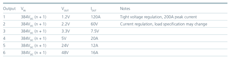
Next, tabularize the system operating voltages, currents and power levels. Do this by listing the loads and organizing them according to the required output voltage and the loads’ current requirements.
It is also useful to begin thinking about specialized functions that may be required. In the example below, there is a point-of-load at 1.2V with a 120A current requirement. That particular load has a tight regulation requirement and can experience up to 200A peak current. The second example is a 2.2V load — an LED driver, for example — which must be current-regulated.
Develop a power delivery architecture and begin to select and finalize the power modules needed to fulfill the system conversion needs. Construct a block diagram of the system and settle on an architecture for providing power from source to load.
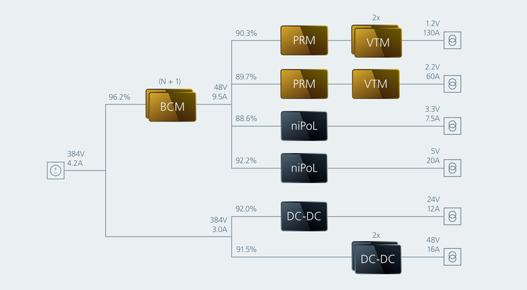
Begin by laying out the system outputs, as shown on the far right side in the figure below. The points-of-load range up to 48V, 16A. A review of the available power modules on the market makes it possible to decide what classes of modules are appropriate to supply those loads.
Basic system architecture using load characteristics and estimated efficiencies to establish module requirements.
Basic system architecture using load characteristics and estimated efficiencies to establish module requirements.
Next, consider some of the physical constraints of the system. This can include things such as the available space for system implementation, design considerations for isolation requirements, and whether or not it will be possible to take advantage of specialized power delivery network (PDN) architectures. Factorized power (an architecture developed by Vicor) is shown in this example supplying some of these points-of-load using a 48V bus.
With the loads laid out and the point-of-load regulators and power modules in place, it is possible to begin working backward from the load side to the source, using data sheet efficiency estimates for each load branch to formulate the current output requirements of the upstream conversion blocks. Working towards the 48V bus from the points-of-load, the block diagram indicates that the system will need to supply at least 9.5A of current from the bus converters, and effectively sets the requirements for selecting modules.
More refinements may be necessary as part of this design. For example, the 2.2V load where the load specification could change, perhaps doubling the required current for that load. This is easy to solve with a modular approach: simply double up the voltage transformation modules to satisfy the new design requirement. Adjust the efficiency estimates and the load requirements on the upstream bus converters as needed to form a picture of the overall system design.
At this point in the design process, module configurations and external circuitry necessary for final system integration are finalized. A module or a collection of modules is not a complete power system; spanning the gap from source to load means addressing many areas of concern:
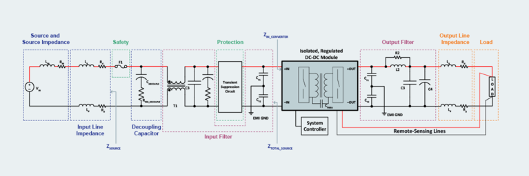
Determining what these concerns entail is where the bulk of the design work is done. Start by examining an idealized example of supporting circuitry, which for simplicity is shown around a single DC-DC module.
Example of supporting circuitry required to build a complete system with DC-DC power modules.
Example of supporting circuitry required to build a complete system with DC-DC power modules.
Working outward from the power module, designers must first mitigate the noise characteristics of the switching converter, which includes input- and output-side filtering. Second, ensuring system stability requires analysis of power source and distribution line impedances in order to provide appropriate decoupling of the source from the regulating power module. Additional support circuitry may be required to meet safety requirements and protect the system from surges and spikes, depending upon the operating environment. Finally, any special load considerations must be accounted for in the system design.
The final stage of the design process is interacting with the modules, tailoring behavior and managing the control and monitoring interfaces. Power modules have various signaling and low-voltage I/O capabilities: analog interfaces and digital interfaces for interacting with the modules.
A typical analog interface for a power converter provides access to various control capabilities – output voltage trim, for example. There may be an enable pin that can be connected to an external controller, as well as basic monitoring capabilities in the form of a fault flag pin. The module might provide a representative voltage that corresponds to an internal temperature monitor.
For more detailed monitoring information and control, many power modules offer PMBus® over a digital interface, which provides output voltage trim control, enable/disable control, and other configuration options. Set points for current-limit threshold and fault protection may be available, which makes tailoring the module behavior to specific application needs possible. Additionally, digital fault-status flags give a better capability to identify fault causes such as undervoltage, overvoltage or overcurrent events.
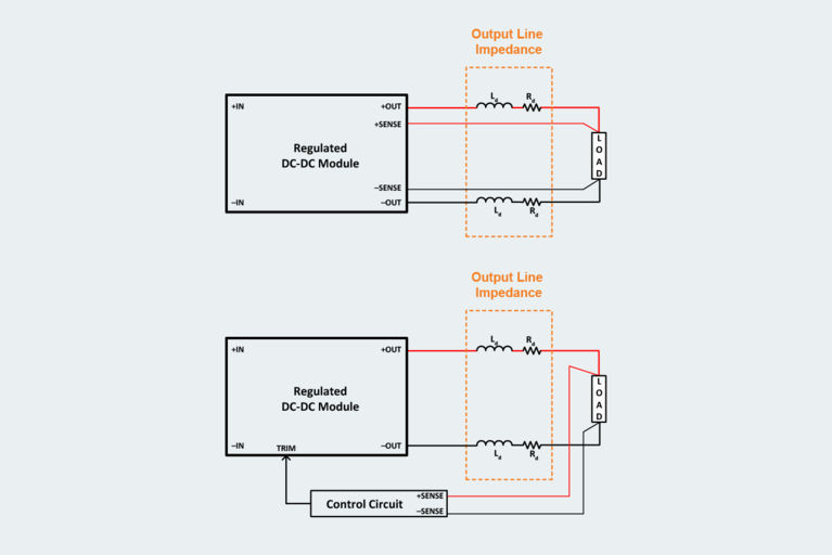
Regulated modules often provide remote-sensing capabilities that enable tighter regulation at the load by compensating for distribution line impedance drop. Remote sensing makes use of a Kelvin connection of two sense leads that monitor the voltage directly at the load terminals so that the controller can offset voltage drop in high-current distribution systems.
Analog and digital signal capabilities with power modules.
Analog and digital signal capabilities with power modules.
Irrespective of analog or digital control signaling, it is important to differentiate the grounds to which the power signals and low-level signals are referenced. If a low-power signal-level connection shares a common ground return path with the module’s power output, high-frequency noise from the switching action of the module can be coupled into the signal due to trace parasitics and cause erratic operation. To prevent the power current from flowing through the signal ground, connect the signal ground and the power ground at a single point only.
Having completed this general overview of the design process for systems that employ DC-DC power modules, the following series of tutorials will address in greater detail the major considerations of the third design stage.
Also in this series:
How to design modular DC‑DC systems, part 2: filter design
How to design modular DC‑DC systems, part 3: stability analysis and decoupling
How to design modular DC‑DC systems, part 4: safety protection systems
How to design modular DC‑DC systems, part 5: load considerations
Innovation: Factorized Power Architecture
Innovation: 48V direct to low voltage conversion
Video: Why are power designs moving to 48V?
White paper: Attributes of high‑performance power module packaging
Optimizing DC-DC converter stability: AC and transient analysis in simulations of source impedance effects
Learn how to optimize DC-DC converter stability through AC analysis in the frequency-domain and transient analysis in the time-domain
Power modules simplify creepage and clearance design solutions for electric vehicles
Overmolding is the key to solving arcing issues in 48V automotive power systems
Current multipliers: The obvious choice for powering AI processors and other demanding applications
AI processors need to handle low-voltage, high-current demand, which can cause power system bottlenecks. Learn how current multiplication can change that.
High-performance ZVS buck regulator removes barriers to increased power throughput in wide‑input-range point-of-load applications
Today's higher performance applications require more than what conventional regulators can offer. Learn how ZVS topology can boost your performance.

