By Phil Davies
Power distribution networks (PDNs) are the backbone of any power system. As system power demands rise, traditional PDNs are under tremendous pressure to deliver enough performance. There are two main ways to improve PDN impact on power system performance with regards to power losses and thermal management. Option one, reduce the PDN resistance with larger cables, connectors and thicker motherboard power planes; or option two, boost the PDN voltage to reduce its current for a given
power delivery, which can allow use of smaller cables, connectors, motherboard copper planes and their associated size, cost and weight.
For many years engineers have used option one for compatibility with the large ecosystem built up over decades for single-phase ac and 12V DC-DC converters and regulators. Other reasons include the lack of performance of DC-DC converter topologies that could efficiently convert higher voltages to PoL (point‑of-load) directly and the associated expense of these higher-voltage converters and regulators.
However, modern-day power designs increasingly use option two, higher PDN voltage. This trend is driven by the significant rise in system load power. In the case of data centers, the addition of artificial intelligence (AI), machine learning, and deep learning has caused rack power to soar by a factor of two into the 20kW range; and supercomputer server racks are now approaching 100kW or more.
Figure 1: The ideal point-of-load power system. A regulator delivers top efficiency when VIN = VOUT.; maximum efficiency comes when high-current delivery is closest to the point-of-load, minimizing I2R losses.
This increasing need for power has systems engineers point‑of-load their complete PDNs, from the distribution of power to the racks, power distribution within the rack, and even the PDNs on the server blades because modern CPUs and AI processors consume more power. When rack power was at a 5kW level, single-phase AC to the rack was the norm. The AC was then converted to 12V for distribution to the server blades. At the 5kW level the PDN current was 416A (5kW/12V) and power distribution took
place via heavy gauge cables.
As processor power started to dramatically rise around 2015, rack power moved up to the 12kW level. So 1kA had to be managed within the rack for a 12V PDN. The OCP (Open Compute Project) consortium – whose membership includes most cloud, server and CPU companies – continued to evolve its 12V rack design. OCP racks moved from cables to bus bars and distributed multiple single-phase AC-to-12V converters within the rack to minimize the PDN distance and resistance to the server blades. The major change from prior rack power delivery was that the single-phase AC was derived from the individual phases of a three-phase feed to the rack.
Companies with the ability to build their own racks and data center solutions began to move to 48V distribution. This strategy cut down the high-current PDN problem to 250A for a 12kW rack but brought new challenges to blade power conversion.
Figure 2: High current delivery through the “last inch” imposes obstacles on high-power processors. Vicor technology improves this performance and simplifies motherboard design.
As rack power has risen above the 20kW range, server rack PDN design is continuing to evolve. Attempts to maintain the status quo 12V legacy systems are creative on many fronts, but the introduction of AI into data centers with processors exceeding 1kA steady-state with peak currents approaching 2kA make 12V-based PDNs impractical. AI is all about performance, and 12V PDNs limit performance and competitiveness.
To address the many challenges of high-power racks, the OCP consortium is evolving toward racks that accommodate 48V PDNs. Moving to 48V from 12V distribution reduces the input current requirement by a factor of 4 (P = V × I) and cuts losses by 16x (power loss = I2R). Moreover, there’s a move to 48V power distribution in the automotive and 5G markets, LED lighting, display markets, and in industrial applications. Thus the ecosystem of 48V power converters is rapidly expanding. Moving to 48V makes good business sense. However, not all 48V converter topologies and architectures are the same. Performance varies widely in the 48V converter market, a fact worth carefully considering.
With high-performance and power efficiency at the top of the list of requirements for high-power racks and data centers, several companies are moving to three-phase-AC-to-48V for distribution to the blades. Alternatively, high-voltage DC (at 380V, derived from a rectified three-phase feed) distributed within the rack can be used. Several high-performance computing (HPC) companies are using HVDC PDNs for racks up to 100kW.
As PDNs that supply the blades convert to 48V, power conversion on the blade must change. This shift has led to many alternatives in architecture, topology and packaging of DC-DC converters and regulators.
The 48V regime is new to data center servers but commonplace in communications applications such as routers and network switches, thanks to their use of –48V lead-acid rechargeable backup-battery systems. The common architecture traditionally used in data center servers was called the Intermediate Bus Architecture or IBA. IBA consisted of an isolated non-regulated bus converter to convert the –48V to +12V which was then fed to a bank of multiphase buck regulators for the points-of-load. Some of the
cloud computing companies and HPC companies copied this architecture initially for their 48V systems, but as power rose and voltage at the PoL dropped to 1V and below, designers sought out alternative architectures and topologies.
Power system architecture, switching topologies, and packaging are critical to a high-performance, high-density design. As AI and CPU processor currents rise, the density of the power delivery circuits at the PoL becomes the most critical element in AI applications because of the PDN resistance between the regulator and the PoL.
The latest state-of-the-art AI processors have steady state currents of almost 1kA with peak currents reaching 1.5 – 2kA. Consider that a typical PDN resistance from the output of a conventional multiphase buck regulator to the processor is in the 200 – 400μΩ range. The resulting power losses in the PCB are 200 – 400W steady state (P = I2R), too high for any system to handle.
PDN losses become the dominant factor in the efficiency and performance of the DC-DC regulator design. Because this is a point-of-load problem and higher voltage is impractical (PoL voltages are declining rapidly to keep Moore’s law in force), the only reasonable approach is to reduce the PDN resistance, usually by placing the regulator as close as possible to the processor. In the case of a multiphase buck regulator, it typically takes 16 – 24 phases to support the high AI processor current. This is not a high-current-density approach and does not solve the PDN power loss problem.
Factorized Power Architecture
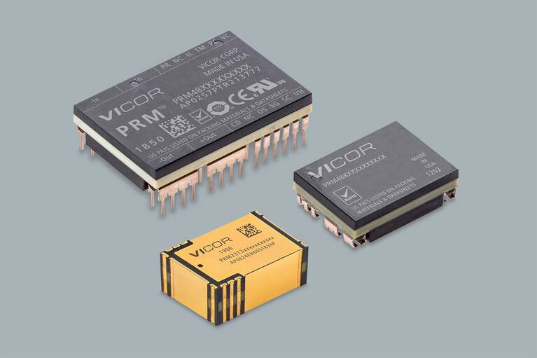
An alternative to IBA is the Vicor Factorized Power Architecture (FPA™), which consists of a preregulation stage (PRM™) followed by a voltage-transformation stage (VTM™). This proprietary architecture optimizes the performance of each stage. The PRM performs a non-isolated (48V is Safety Extra-Low Voltage, SELV) regulation. Its 48V input is tightly regulated to provide a 48V output, and conversion to the desired PoL voltage takes place in the VTM, which is a fixed-ratio converter (the output voltage is a fixed ratio of the input voltage).
Figure 3: MCM modules can deliver high current and can sit adjacent to the processor either on the motherboard or on the processor substrate; this close placement minimizes PDN losses and reduces the number of processor substrate BGA pins required for power.
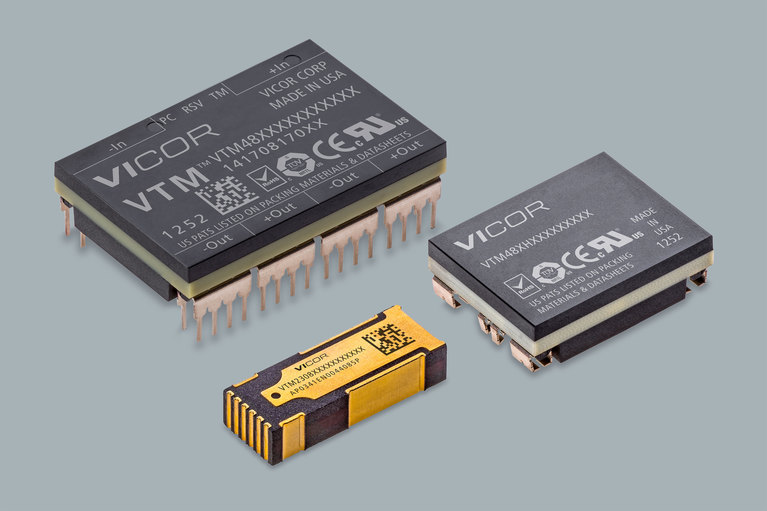
This architecture and its performance are enhanced by proprietary topologies used within the PRM and VTM. The PRM uses a zero-voltage switching topology while the VTM uses a proprietary resonant high-frequency Sine Amplitude Converter (SAC™) topology. Conversion to the PoL voltage uses both zero-voltage and zero-current switching. The VTM is essentially a DC-DC transformer where the voltage is reduced with the ratio of 1/K and the current is multiplied up by the K factor. The VTM, also known as a current-multiplier, is a high-current-density PoL converter. (New products currently hit 2A/mm2). It can sit extremely close to the processor because of its innovative ChiP™ packaging technology and high‑density integrated magnetics.
This level of high current density offers designers great flexibility. Depending on processor current, engineers can choose between lateral or vertical power delivery (LPD and VPD). In LPD, the current multiplier sits within a few millimeters of the AI processor either on the same substrate or directly on the motherboard, reducing PDN resistance to approximately 50μΩ.
Figure 4: Vertical Power Delivery (VPD) further eliminates power distribution losses and VR PCB area consumption. VPD resembles the Vicor LPD solution with the added integration of bypass capacitance into the current multiplier or GCM™ module.
For even higher performance, VPD moves the current multiplier directly beneath the processor where it’s output power pin map matches the pitch and location of the processor power pins above it. The current-multiplier package also integrates the high-frequency bulk capacitors that typically sit beneath the processor on the motherboard or substrate. This type of current multiplier is called a GCM (Geared Current Multiplier). VPD reduces the PDN resistance to an incredible 5 – 7μΩ, enabling AI processors to realize their true performance capabilities.
Conclusion
Complex power problems of this magnitude require a holistic design approach to deliver successful high-performance results. It takes innovations in architecture, topologies and packaging to solve the toughest power challenges. Higher-voltage PDNs can solve many system performance challenges. A reduction of PDN resistances is the key to unlocking the next generation power for HPC and enabling the promise of AI.